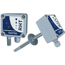
Novus RHT Wall Mount and Duct Mount Humidity & Temperature Transmitters
description
The RHT Relative Humidity and Temperature Transmitter converts these two physical parameters into two industry standard, isolated, highly stable and interference free 4 to 20 milliamp signals. The sensors are mounted on the probe tip (protected by a polypropylene filter cover) and are unpluggable and washable. Both outputs are two wire transmitter loops, requiring a 24Vdc (nominal) supply in both loops. The same pair of wires that supply power to the circuitry then carry the signal to the measuring device. The two outputs would normally be used as inputs to PLCs, controllers, digital indicators, data loggers or SCADA or telemetry systems.
specification
Relative Humidity Circuit
- Output: 4-20mA for 0 to 100% RH
- Power supply: 12-30Vdc 2 wire
- Accuracy: ±2.8 from 0 to 100% RH at 25°C
- Repeatability: ±0.5% RH
- Linearity: ±0.5% RH typical
- Maximum hysteresis: ±1.2% RH
- Stability: ±1% RH typical at 50% RH in 5 years
- Humidity measurement temperature drift: RH (compensated) = RH (measured) / (1.0546 - 0.00216 * T) RH in %, T in °C
- Time constant: 15 seconds in still air
- Operating temperature: -20 to +80°C max(electronics housing)
- The built-in humidity sensor may be damaged or lose calibration if exposed to chemically active environments such as: Ammonia hydroxide, Acetone, Ethanol, Methanol, Formaldehyde, Benzene, Toluene or Xylene
Temperature Circuit
- Output: 4-20mA for -30 to +70°C (default)
- Power supply: 12-30Vdc 2 wire
- Sensor: PT100
- Accuracy: 0.25°C
Dimensions and Mounting
IP65 grey ABS enclosure, 60 x 60 x 35 mm; sensor: 13.7 (dia) x 150 or 250 mm. The unit is installed with an included flange. The flange is secured to the duct wall and then the probe pushed through the flange to the required depth. After positioning probe a lockscrew on the flange can be tightened to lock it in place.
Connections
Note that each independent transmitter (RH and temperature) needs only a two-wire connection to a power source (12Vdc to 30Vdc). The 4-20mA measuring signal flows through the same two wires taking the signal to the measuring device. The power cable passes through the cable gland and is attached to the screw connector according to the instructions on the inside of the enclosure lid. The maximum LOAD resistance plus the wires resistance can be calculated as: LOAD = (Vdc -12)/0.02 ohms (where Vdc is the voltage of the power supply).
Re-Ranging
The RHT-DM is supplied ranged 0 to 100% and -30 to +70°C as default. The TxConfig adaptor and Windows software, allows you to configure the instrument.
downloads
Novus RHT Flier
Novus RHT Manual
RHT Configuration Software v1.70
